Super Triode Connection FX
7044 CSPP amplifier - class AB1 -
1. CSPP output stage
In 1952, Mr. Shimada invented CSPP , the Cross Shunt Push Pull topology, when he was still under graduate. Subsequently he was awarded patent for the circuitry by the Japanese authority, however, failed to attract any interest from local industry.
In 1954, Electro Voice announced a similar design under the name Circlotron.
The difference between Shimada's topology and EV's lay in DC path, AC path was arguably equivalent. In my opinion, Shimada's CSPP was the clear winner for the audio application.
To be historically correct, the topology should be referred to as CSPP. Alas, before seeing the recognition by the community at home and abroad, Shimada passed away at the dawn of the millennia, all the more reason for the recognition.
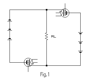
The basic CSPP topology looks like this:

This configuration is free from the drawbacks found in the DEPP topology. For the DEPP see here STC-MX of 2a3-pp.
As a not so well known advantage over the DEPP, CSPP can accommodate the output transformer of the lower primary impedance, 1/4 for the equivalent power rating. Lower primary impedance generally transpires to better behaving transformers, extended smoother high-end, less power loss, and higher damping factor, to name a few.
1-1 Driver for the CSPP
Fig.1 comes to mind readily. Deceptively conventional grounded cathode,
however, requires floating bias voltage source, serious concern for noise
susceptibility.
Self biasing comes next, promising in this regard, but at the cost
of zero voltage gain at this state. Not practical unless you can afford
the drive stage positive rail potential more than twice as output swing.
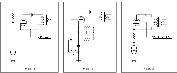
The simplest method is figure 2. The final stage has gain mu of final
tube.
But fixed bias can not be used, and the cathode bias of this circuit
needs very large capacitor, otherwise the low frequency response will be
restricted by the bias circuit.
The circuit figure 3 is fixed bias, it looks like SRPP or mu follower,
but final stage has a gain (mu), because plate to cathode or cathode to
grid voltages of final stage are not concerned to the drive stage. So this
circuit is almost boot-strap circuit.
Moreover, the driver stage current is added to the power like as SRPP.
However, this circuit has a disadvantage.
As original CSPP is very low output impedance, and this is one of the
advantage of CSPP.
However, the circuit of fig.3 is not low output impedance.
Clearly internal resistance of this circuit equals to the rp of final
stage tube.
1-2 Super Triode Connection FX
From above reasons, I considered if I had employed triode instead of
the current driver in fig.3.
A triode has an internal resistance rp, so its output impedance is
the middle of voltage drive and current driver.
If the rp is smaller, CSPP output gain will be decrease and output
impedance will be smaller.
The output device operation of this circuit could be called "half cathode follower", so CSPP stage has some gain, and internal resistance is larger than cathode follower but far smaller than ordinary common cathode amplifier.
By constructing differential amplifier of triode for the drive stage, the unbalance of output transformer is feedbacked through the rp of opposite side of differential, because the each side of output transformer is reversed, and the differential of triode is connected by common cathode.
Please refer to the following figure, this is the current (Norton) model of proposed amplifier.
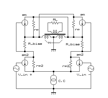
The equivalent circuit shows that the differential DEPP and SRPP and
CSPP are combined.
I named STC-FX: Super Triode Connection FX, F stands on the 'floating
amp', and X is Cross Shunt PP.
At first I imaged the name 'DCSRPP' (Differential Cross Shunt Regulated
Push-Pull), but it does not sound nice, furthermore, I love the name of
FX because of old Kawasaki motor cycle Z750FX. ;-)
The name of 'Super Triode Connection', which is invented by world famous
'guru' Kamijyo, and he defined that the STC is the feedback amplifier using
rp of triode.
So this amplifier is conformed to his definition, although far different
from several circuits of STCs those of his own designing.
The basic idea of STC is here.
I have employed the 7044 tube for the final stage, this is the double
triode MT tube and each Pp=4W (both operation). This tube was basically
made for the computer, but its characteristics are quite good for audio
usage.
Here, internal two units are used for push-pull.
And 6463 for the driver stage is also computer tube, this tube has high reliability and very good linearity with low rp.
2. Design of the amplifier
2-1 Output stage
Below figure shows the load line of output stage.
As I can not get the detailed data of 7044, so here I use the data
of 5687, which is almost same characteristic.
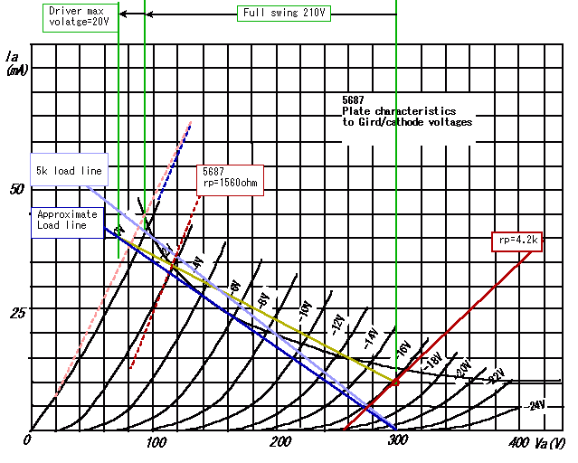
The Calculated maximum power is around 4.4W.
The mu of 7044 is larger than 5687, and maximum current also large,
so probably the line of Vg=0V would be like as dotted pink line.
Please notice, the load impedance is whole impedance but not a quarter
of transformer.
You can find three lines. Light blue line shows the 5 [kohm] load,
but the driver current is added to this line by the proposed method, so
dark blue line is assumed for this load.
Operating centre point is defined 10 [mA]/300 [V], so dark khaki line
can be drawn if it is A class, but class AB1 operation, true line is 'curved
line', just the middle of dark khaki and dark blue lines.
The peak operation voltage from centre of the driver stage is the half of this line, because the output voltage of one side for differential driver is the half of CSPP, so plate AC voltage is almost +/-100 [V] for peak to peak for one side.
The plate characteristic of 5687 is very similar to 7044, but you can
not use the 5687 for this amplifier, because the maximum rating of heater
to cathode peak voltage is inferior to 7044, and maximum plate power consumption
is also.
Peak heater to cathode volts of 7044 is +/- 200 [V] maximum (absolute),
but 5687 is +/-100 [V].
By the Raytheon catalogue of 7044, each ratings are absolute maximum, but not design centre value. Please be care.
2-2 Driver stage
Herewith please find the load line of driver stage tube 6463.
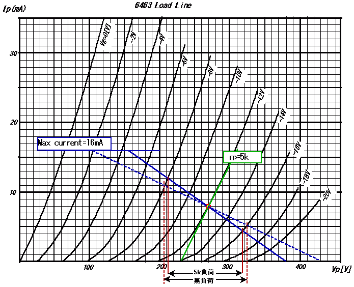
You can know the output voltage from this figure, but the voltage of driving resistor (Cathode resistor of final stage) should be subtracted from this figure.
The equivalent circuit shows the plate of driver stage is connected to cathode resister and transformer, but the load impedance can not be calculated from the resistor value and transformer impedance. CSPP power stage flows current to the transformer, so the output current is driver stage current plus CSPP final stage. The output power is produced from these current.
This circuit looks like SRPP, but the load line is very different, because the current of final stage flows to transformer, but it does not flow to driver stage.
Blue solid line shows the 5 [kohm] load for final stage, and the blue
dotted line is the output voltage without load (infinite impedance).
The damping factor can be calculated from this figure if ignored the
DC resister of transformer.
The output impedance of STC-FX is strongly related to the rp of driver
stage as you can find.
In other words, the rp of driver stage is a feed back resister for
the power stage - that is just the idea of Super Triode Connection -.
Therefore, the output characteristic is the enlargement of driver stage
basically, which means the characteristics is similar to the differential
output of triode, but more power and lower internal resistance, lower distortion
can be gotten.
3-1 Amplifier circuit
Please find below circuit which I made.
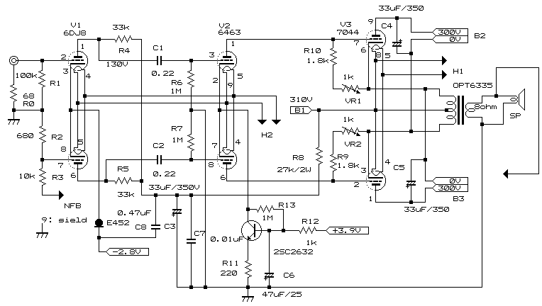
The first stage is 6DJ7. The low rp and high mu are necessary for this
stage, because the output swing voltage of driver stage is almost same
as output, so the grid to plate capacitor of driver stage is enlarged strongly
by the Miller effect.
The CRD (Current Regulated Diode) is employed for the common cathode
of the fist stage, in order to get higher CMRR of differential.
Negative power supply is used for this stage because bias voltage of
6DJ8 is small.
Negative power is necessary for the constant current stable enough.
The transistor is used for the second stage constant current, and you can not used CRD for this stage, because CRD shows negative resistance in high voltage/high current usage. It might bring the over heat accident.
Calculated maximum NFB would be 12 [dB], but the transformer was cheap one and its characteristic was unknown, so I forecast 6 [dB] would be suitable.
To be honest, beam tetrode or pentode will be more suitable for the
power stage by this method.
Maximum power will be increased dramatically, and distortion will be
decreased.
Basically, differential output stage works different method whether
triode or pentode.
Triode differential corrects the inverted voltage each other and correct
its balance through the rp, but pentode does not. This is a kind of feedback
through the rp.
However, with proposed method, CSPP output stage is not concerned to
this balance, but only a driver stage concerns, so pentode has an advantage
for this method.
Then, why did I use the 7044 triode? The reason is very simple, I have had it :-)
3-2 Power supply
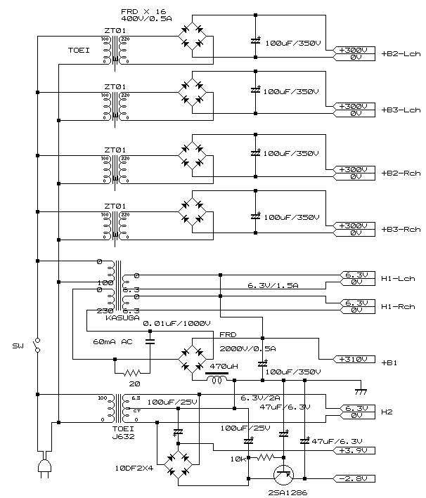
The power supply circuit is very complicated, because it needs floating
4 power supplies for stereo. I used individual power transformer, and the
each transformer was designed for AC voltage converter for Japan to Europe.(Japan:
AC100V, EU: AC220V)
These transformers are very cheap, but they have enough performance.
I have got the negative power supply for the first stage by rectifying
the heater transformer, but please notice, the allowable ripple voltage
is really small.
Ripple voltage level of the rectifying output is around 0.2 [Vp-p]
but the ripple voltage will be suppressed around 1/30 by the constant
current of CRD, and the gain of the first stage is almost 26[dB].
If the differential gain error is 5%, output hum level will be 2 [mV]
from above data.
It will not be acceptable.
Therefore, I used the transistor for the ripple filter. High hFE
type should be used, the hFE of chosen transistor is 500. If
you want to use smaller hFE, the resistor value to the
base should be also smaller.
I used the small inductor designed for the switching regulator. This
power transformer was a little bit small for my design, so power factor
had to be improved than conventional rectifying circuit with capacitor
input.
I used this method just in the last resort, but from the experimental
result, I was surprised that it was effective for increasing the conductive
angle.
Of cause it is discontinuous conductive mode, so the output voltage
is not regulated by the inductor.
This method has an advantage for noise also, because the reactive power
becomes noise current.
Here, [reactive power] = [apparent power(VA)] - [effective power(W)].
3-3 Others
I used a too small chassis to implement fuse, but you have to use fuse
for each transformer if you want to try :-)
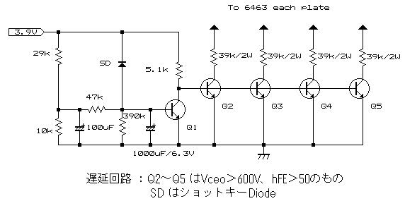
The driver stage has to be switched on before final stage, otherwise
final tubes will be broken.
Therefore, heater transformer does not pass via the power switch, but
below circuit may be better for this purpose.
4 Test result
Damping factor is around 8 (2 [V] / 7.5 [ohm] load), although the
NFB is less than 5 [dB].
The data shows that the proposed method works effectively.
Maximum output power is around 3.5 [W]. This is less than calculated
value, because the AC voltage in my home is too much lower than normal.
Voltage gain is almost 16 dB, so maximum power can be gotten around
at 0.8V.
Noise level is 0.28 [mV] without any filter. This is no problem for
listening music, but I am not satisfied with this value. I think floating
power supply may be concerned to the noise.
The total harmonic distortion at 1 [kHz] is here.
The sound character is very natural even though the circuit is not normal
:-
The output power is so small, but the sound is powerful enough.
You may ask why, but do not ask me! I do not know why.
Please notice, this circuit is not easy to make if you did not use to
make amplifiers.
If you want to make this amp, please try it by your own risk.