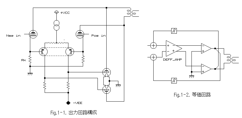
Below left figure shows the basic circuit diagram, and right one is the equivalent circuit of this method.
Super Triode Connection MX
2A3 DEPP amplifier - class AB1 -
Recently, a tube amplifier with using differential output seems to be
popular in Japan.
The purpose of this circuit is clear, it is 'complete push-pull balance'.
Conventional style double ended push-pull (DEPP) is balanced by an
output transformer, but a transformer can not realize complete balance
because of its loss.
When output tubes add the power to the transformer, a part of the power
consumed for heating transformer, and such a loss makes an unbalance.
Of cause single ended amplifier does not need to think about this balance, so I think this is one of the reason why some 'audio dilettantes' like a single ended amplifier.
I do not doubt that good balance could be achieved by a differential,
but clearly it has some disadvantages.
For example, the maximum power will be decreased smaller than conventional
A class DEPP with fixed bias. The third harmonic distortion will be increased
when close to maximum power, and so on.
Here I propose an amplifier with using 'STC' method to overcome above
issues of differential with keeping complete push-pull balance.
I made an amplifier with this new method and named Super Triode Connection
MX for this topology.
M stands on "Modoki", which means 'pseudo' or 'similar' in Japanese,
and X means 'crossed'.
If you do not understand STC, please read the principle of STC.
In principle, the basic idea is just a differential amplifier, but I
realized with using the feedback of STC.
Below left figure shows the basic circuit diagram, and right one is
the equivalent circuit of this method.

In the equivalent circuit, I wrote a feedback constant beta, which is
realized by the triode. The whole gain of this circuit nearly equals to
mu of the feedback triode, and push-pull feedback lines are "crossed" each
other, so the CMRR (common mode rejection ratio) is higher than conventional
tube differential amplifier. Then, the output push-pull balance should
be better also.
In general, CMRR of this amplifier is far better than the coupling
coefficient of transformer, and the feedback is not concerned to the loss
of transformer's.
Furthermore, in order to realize the STC push-pull amplifier, the most
important point is PSRR (power supply rejection ratio). Because, STC has
very low internal resistance, which means if the PSRR is not enough, large
current flows to output tubes.
Surely, this is a dangerous situation.
The proposal method has a quite high CMRR on the power stage, and high
CMRR means high PSRR.
However, as this circuit is connected directly with the second stage, it has a disadvantage for the stability of bias voltage of output tubes. Therfore, I added the DC bias servo circuit in order to overcome this issue,.
Furthermore, the linearity of the circuit in this figure will not so
good, because the linearity of this amplifier will be close to the triode
differential amplifier without feedback.
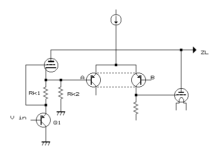
In order to get lower distortion, I added the emitter follower to drive
the feedback triode. Of cause frequency response becomes wider by the low
impedance of the follower.
 Figure
2
Please refer to the figure 2 above, which shows the driving circuit.
By this method, the load line of feed back triode can be drawn with
opposite angle to the line of conventional differential amplifier. That
is, when Vpk becomes higher voltage, the Ip current flow is larger.
Below figure is the load line of the feedback triode 6463 in designed
amplifier.
6463 is the computer tube, but it has a very good linearity and of
cause high reliability, furthermore its high maximum rating is suitable
for the feedback triode.
A red mark is operating centre point.
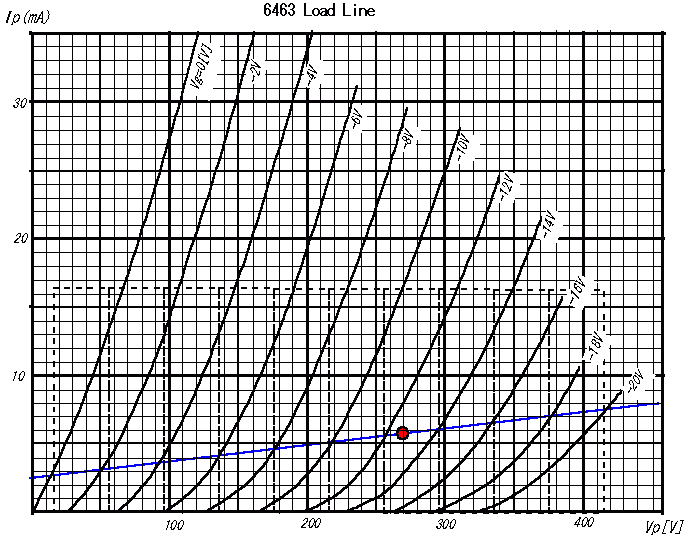
Dotted lines are written with the same interval, divided by a mu = 21.
As you can see, the linearity is unbelievable.
This is the line of single tube, but the feedback is push-pull. Therefore,
the unbalance of both sides from the operating centre of this line would
be suppressed each other.
We are occasionally going to end up with nothing when designing a tube
amplifier if trying to achieve both.
However, here you can find that we can achieve both by the assistance
of semiconductor. If you adhere inflexibly to the tube without semiconductor,
you can not get both.
The designed circuit of amplifier is shown below.
I employed differential amplifier of 6DJ8 (ECC88) for the first
stage. A conventional feedback is used together, to get better balance
for the first stage.
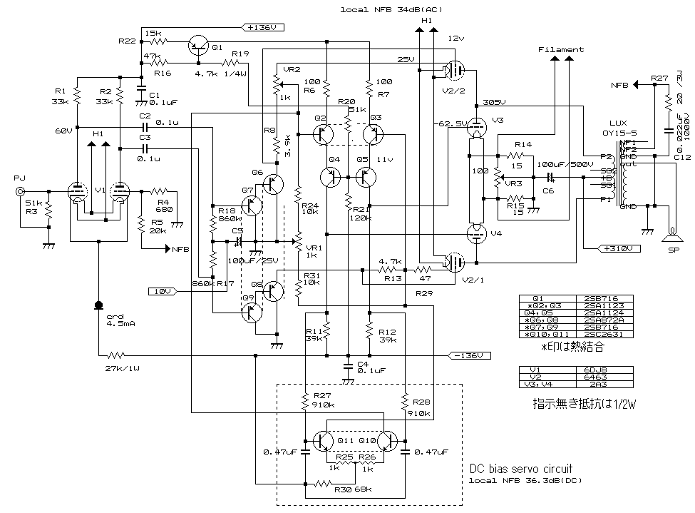
DC bias servo is working to be the same bias voltage for each side of push-pull. It works against the unbalance of DC due to controlling the current of feedback triode. Probably you have never seen this style for DC servo, but it works sufficiently.
The final power stage is 2A3, and the local NFB with STC is around 34
dB.
Therefore the output impedance of the final stage is around 12 ohm
or less for differential output, however bias current is very stable due
to the quite high CMRR and DC servo rather than conventional DEPP amplifier.
Please notice, if you want to try to make a push-pull amplifier with
STC, you have to consider about the bias current stability.
Transistors for differentials should be jointed each other for thermal connection.
There is no need any protection circuit like as conventional Loftin-White amplifier, because the bias voltage of 2A3 final stage equals to minus power supply whilst the feedback triode is cold.
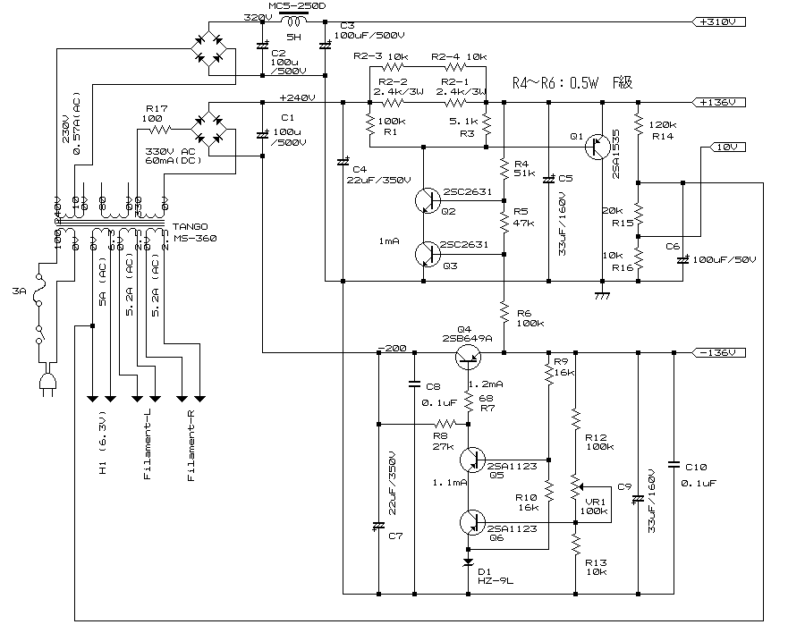
Except for the final power stage, I employed the semiconductor regulator
for the voltage power supply.
This regulated power supply is also new circuit, which I developed
for this amplifier, because the output voltage of the power transformer
is too high for my circuit.
I used the power transformer of TANGO that my friend gave me, but of
cause there is no need to use this transformer and also no need to employ
regulator, if you want to try this amplifier and if you have suitable power
transformer.
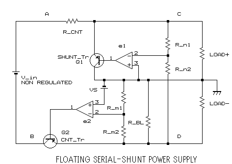
The floating shunt regulator and series regulator constructs this new
regulated power supply. Please see above equivalent circuit. Basically
input voltage has to be higher than output voltage, and the voltage of
Q2 is almost same as the voltage of both sides of R_CNT, if the positive
current is almost same as negative's.
A transistor Q1 needs some bias current for the operation, so R_BL
is the bleeding resistor for this purpose.
In the real circuit, bias current of a Zener diode substitutes for
this part.
I named SSPS circuit for this regulator.
I made below circuit based on the principle written above.
The voltage stability is quite good for temperature and supplying current.
I am satisfied with the performance of this amplifier.
Damping factor is 16 at 8 ohm. If using an output transformer currently
designed, this value will be better than 20. (The output transformer was
designed in 40 years before, almost same age as me! :-)
Noise level is smaller than 180 micro volt without any filters, 10
Hz to 200 kHz meter range.
Clearly this performance depends upon a method of STC-MX.
The total harmonic distortion at 1 [kHz] is here.
The sound is very clear, but silky. Especially, it is good for the transient
sound.
It is difficult to explain this sound character, but attractive.