This document reports the experimental result of Cross over network with 5th order elliptic filter .
It is quite natural requirement to achieve the sharpest slope filter with the given order, for example limited to use 5th order filter.
The elliptic filter is the answer of this requirement.
However, to tell the truth, few people can understand if I explained about the mathematics of the elliptic filter, - it is called "Jacobian elliptic function" - , except for the engineers or scientists who had learned about this function. This is really difficult theory.
"The elliptic function", you can learn the "elliptic integral" at physics lecture in the university, in order to think about the swing of the pendulum. There are two types of elliptic integrals, Legendrean and Jacobian, and for each types there are also two types, the first kind and second kind elliptic integrals.
Here, the first kind order Jacobian elliptic integral is simply shown by sn-1(x), this is called the Jacobian elliptic function. ("sn" is named by the similar behaviour to the sine, and another type "cn" is similar to cos.)
By using this Jacobian elliptic function sn-1(x), we can theoretically demonstrate that the sharpest filter can be achieved.
Prof. Cauer found and proved such mathematical theory, so it is sometimes called "Cauer filter".
Please read the book of filter technology if you want to know details.
By the way, the 1st kind order Jacobian elliptic integral, it is not only to difficult to understand but also we cannot get the answer of the function with elementary method, like as substitution the value for the formula.
Of cause, we can get the answer by the computer with recursive algorithm at present, but in old days when the computer had not been so popular, Saal and Zverev made detailed tables of this filter which is normalized with R=1 and &Omega=1.
You can get the book of this tables but I recommend to read "Electronic Filter Design Handbook" (A.B.Williams, McGraw-Hill) which explains filter fundamentals, method to use this table and the extracts of that table. You can understand everything of this book if you know the Laplace transform and transfer function theory. (This book is not suitable to understand the Jacobian elliptic function or elliptic integrals, but just for design the filter.)
The parameter of design is shown below.
Cross over frequency is 3kHz, and the Saal/Zverev parameters are CO05 20 &theta=30 1-1/K2 (K=&infin), which means 5th order elliptic function with &rho=20% (ripple=0.18dB), Amin=-61.43dB, &theta=30 degree.
Please notice, cross over frequency does not equal to the cut-off frequency of two elliptic filters (0.18dB down point). Cut off frequencies of each filters are 2.5kHz for Low-pass and 3.4kHz for High-pass, the frequencies were defined to get flat response of synthesized characteristic by two filters. And, the "zero" point was slightly moved for the electric components.
Please find the circuit below which was used for simulation.
Circuit diagram for simulation
R3 and R4 are employed for simulation but not required for the real circuit. (in order to DC electrical potential) In the same way, the small resistors R13 and R14 are parasitic resistors to the inductors, but I do not say to insert small resistors.
I already checked the difference of efficiencies with midbass and tweeter, so I employed step-down transformer for the tweeter.
The winding ratio is 2:1, and the DC resistance of tweeter is around 3&Omega, so tweeter impedance becomes 12&Omega by the transformer, this means the distortion will be decreased because the load of amplifier becomes lighter.
Additionally, it decreases unnecessary loss by the attenuator, and electromagnetic damping force increases because of step down transformer.
Furthermore, cost effective capacitor value can be smaller (though inductor becomes larger). Inductor cost is not so different like as film capacitor. This is called "Norton transform" of the filter, we sometimes use transformer for better characteristic with real components or real manufactureing.
In the circuit diagram, the amplifier's output resistor is written because it really affect the simulation result.
And the speaker impedance curve by the fs resonance of tweeter and the inductance of each drivers, they also influence to the filter characteristic, so the filter includes their compensators.
Of cause the fs of the mid-bass cannot compensate, but the influence of this resonance is so small.
R6 and C4 compensate the mid-bass inductance, and C14,R15,C13,R2,L16 are the tweeter's compensator. Tweeter inductance is compensated before transforemer but fs resonance is after transformer, in order to decrease the L value. Otherwise inductance L16 will be very large (around 3mH).
Please find below figure which shows the simulation result of above circuit including compensator.
Green line shows the acoustic synthesis value, and here the tweeter is negative phase.
The slope is very sharp, almost 60dB/oct.
Here, if all compensators are deleted, the filter characteristic can be shown by below figure.
The big ripple near by cross over frequency is due to the inductance of the mid-bass driver, the small peak at high frequency depends on the tweeter inductance, and the rebounding at the stop band of high pass filter is the influence of the fs resonance of the tweeter.
If you understand image parameter filter design or radio frequency design like as impedance matching theory, you may feel it is quite natural, but it is not easy to explain if you do not know.
* As I had written another page, "the circuit diagram is one of the method to show the simultaneous differential equations".
Below figure shows the result of Monte Carlo analysis when 27 degree Celsious and 5% tolerance, 50 times trial.
Monte Carlo analysis is often used to confirm the dispersion of real circuit.
You can find that the dispersion is so small compared to the tolerance of the components, this is one of the feature of the LC ladder network filter, and is called device sensitivity.
I can say no adjustment will be required for this filter when constructing.
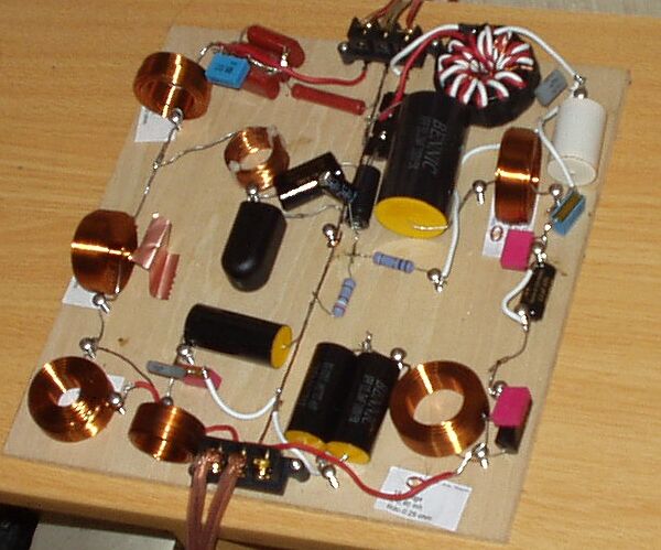
The manufactured filter
I have used many kinds of capacitors, like as ERO, Mundorf, BENNIC, Panasonic and Okaya, in order to prevent the weakness of each maker ··· that is joke;
I just used my stock and I bought at Akihabara if I have not hold, that is all :)
I used Jantzen inductor, which I bought at Yokohama.
However, I was not able to find suitable value for L2 and L4, so I wound them by myself.
You can find no white seal under the inductors.
If you wind by yourself, you should measure and adjustment is necessary.
Generally speaking, Small inductor has high Q factor, so the adjustment is very important.
I also wound the transformer for the tweeter level down, and the core is nanocrystal toroidal core, named "Fine met core". I employed the highest &mu one.
I used twisted pare cable with thin plastic jacket, in order to construct the automatic transformer with bifilar winding.
The primary winding is the 28 turns, and the saturation magnetization can be got at 45Vpp/1.5kHz. This is just suitable for my usage.
The primary inductance is around 68mH. It is quite large but we cannot use very low frequency because of the saturation magnetization. More turns is required for lower frequency, but difficult to make.
I cannot measure the high frequency response of this transformer because it is better than my measuring equipment. This fact shows remarkably high coupling coefficient.
The loss of the power is less than 0.1dB at 2k to 150kHz, so it is neglectable.
The price of this core is unbelievably expensive, but this is highest grade transformer for the tweeter, so I cannot get this quality with other method.
I think normally you cannot buy this core, but big toroidal ferrite core for the power switching regulator will be allowable if you turns twice of mine. (Please be care, the ferrite core for the power regulator is different from EMC filter's)
I had written this page, it may help you to understand the turns and magnetic saturation.
I used screws for manufacturing, but all the screws are non-magnetic stainless steel.
I used bi-polar electrolytic capacitor for fs compensator of tweeter. The voltage potential is very low at this point, so there is no problem, but please notice other place I do not recommend to use electrolytic capacitor.
This is not only for the sound quality but also for the long term reliability.
To begin with, the capacitor maker company says that bi-polar electrolytic capacitor is not suitable for high speed polarity alternations.
The bi-polar electrolytic capacitor works both potential because the dielectric layer which is created by anodic oxidation is constructed for both side (both anodized), but high speed polarity alternation (AC voltage) brings depletion.
The real circuit I made is shown below.
Still I have not measured the response, but just my impression ;)
Baffle step is not compensated but I wonder that I do not so much feel insufficient low range. It can compensate with preamplifier if you want.
I feel the low range is light. The distortion of the high range is clearly decreased, and I feel it is more quiet.
The tweeter level is slightly higher than previous filter, because the mid range small peak (due to the divided vibration) of the mid-bass is not compensated.
Nevertheless, the sound is more quite and I feel I need more power. (I do not know why :)
The sound is clear and graceful, unnecessary sound is suppressed. However, the sound image is sometimes localized too much centre like as monophonic, if hearing the one point microphone recorded sound.
In general, the advantage of the sharp cut off can be got with the driver which has more high resonant like as metal coned driver.
Back to index
English Home