Japanese English
Wide range two way speaker system
- The design of a transmission line loudspeaker -
The transmission line speaker system (TLS), which is a kind of the enclosure type, seems to be popular recently and increases rapidly.
"PMC" is very famous in Japan, and I use "Meadowlark Audio" which employs also TLS, although this company is not still well known in Japan. (others - many many makers manufacture TLS, but not in TLS speciality)
The biggest advantage of this method may be the extension of low range
and damping, but it should also be mentioned that the sound from the back side of a bass driver does not leak to the front side through the thin cone paper.
In my opinion, it is questionable to the maker's sales message about a
low range, however it is sure that TLS is suitable for extensive low range.
In my design, low range f-3 is 30Hz.
I had seen the data that the distortion is also lower, since it was a little special conditions, so I cannot say it is truth ;)
However, if the acoustic impedance of the back of the driver at low frequency designed fairly high, then cone moving stroke may be shorter, and then the second harmonic distortion may be decreased.
But also in a bass reflex enclosure, we can increase its acoustic impedance,
so it may be dependent on each design.
Additionally talking about damping, both the frequency and impedance level
of the electric impedance peak become lower than bass reflex enclosure,
then Q factor becomes lower, so the good group delay characteristic at low
range also can be mentioned to the feature.
The principle of TLS
Simply saying, the TLS is the long and slender speaker system.
OK, it is the end of explanation... it may be too short ;)
Basically, it uses the principle of the acoustic resonance pipe of an air column, but especially damped by the enough acoustic stuff.
You might had learned the resonance at the science class in an elementary school; If there are two tuning forks, when you sound a tuning fork then automatically another one also sounds.
The difference from a bass reflex enclosure and TLS is that the bass reflex uses the Helmholtz resonance, but on the other hand TLS employs air column resonance at quarter wavelength, and damped sufficiently by the acoustic stuffing.
The bass reflex enclosure is seldom used the much stuffing material for damping.
Although the TLS resembles the back load horn (BLH) in its appearance, but the BLH does not use the resonance neither of the meanings.
(However, it may be resonated unexpectedly in almost all cases ;)
The equivalent circuit of the ideal horn can be shown in Fig 1. The acoustic impedance at the horn throat is the resistive except around the cut off frequency or lower.
The driver back side of the BLH enclosure is resistive load, as it is a horn.
(Here, I mean if the BLH works as ideal horn. For almost all back loaded horn, it may be resonant because it is made by short sections. Therefore, the real BLH is reactive load.)
 Fig.1
The bass reflex enclosure is the reactive load for the driver on its back side.
Fig.1
The bass reflex enclosure is the reactive load for the driver on its back side.
Generally the TLS enclosure will be resistive load for the driver, but it may be dependent on a design. However, it does not mean like as horn load, but it is the effect of the enough acoustic stuffing, and is by the meaning, an acoustic air suspension enclosure is similar to this effect.
Q becomes lower by an acoustic stuff, and the group delay characteristic at super low frequency is also similar to the acoustic air suspension.
Talking about super low frequency group delay, generally a large sized sealed box will be best.
It is large sized to the characteristic of the driver requirement, which means over damping for the driver.
However, although I myself cannot find out any meaning to criticize the group delay characteristics below 50Hz ;-) .
Driver
Since I planed two way, I have searched for 16cm or around this size midbass driver.
As a candidate, I can find Vifa, Peerless, Focal, Morel, SEAS, and Scanspeak etc. -- there are many excellent drivers in this size, not inferior to others.
As I am lowbrow, I decide to employ the driver which is used for the famous speaker system as expensive as possible :-D
The selected drivers are used for Krell LAT-1, it is about 5 million yen in Japan. Its midbass driver is Scanspeak Reverator 18cm 18W8531G00, and the tweeter is Vifa, XT Series 2.5cm XT25TG30-04.
In addition, LAT-1 uses 25cm woofer, so it is three way construction, but my design is two way construction and low end response is expanded by TLS.
The LAT-2 in Krell uses the same midbass driver as LAT-1, but it is two way.
This midbass driver is used for another "high end" system, for instance "Sophia" of Wilson Audio.
The high frequency range of the tweeter is extended to 40kHz or more.
Joking aside, the suitable driver for TLS in recent European drivers, a little bit large Qts may be required (especially the Qms should be).
Therefore, in this size, too large BL value is difficult to use. If a little bit larger size (large effective piston area), we can choose larger BL value but larger size brings worse directivity, so I think it is not suitable for the two way construction.
So, I think "Reverator 18cm" is suitable selection in the Scanspeak drivers.
I have simulated with another Scanspeak driver which has larger BL value, but the low end cannot seem to be flat enough.
If I choose larger size driver, which brings directivity problem as I already written above, but if I choose smaller driver with the same low end response, the efficiency should be lower. Too much low efficiency is not pleased me as I like tube amplifier ;)
The design of TLS
For the design of a TLS box, I used the Mathcad Spread sheet of Dr. Martin
J. King's.
I have never seen the effect of acoustic stuff is strictly calculated before,
so I think his calculation has a value if only alone. (Of cause, there is no meaning without acoustic stuff for TLS)
In short, the method of Dr. King, he divides a line into the section, and then the wave motion equation is solved for each sections.
The following figure 2 is the simulation of the sound pressure characteristic of my design.
I would like to show that the f-3 is 30Hz in order to appeal the design ;)
In figure 2, the dotted blue line shows the characteristic of an infinite baffle, and the red solid line is the simulated characteristic of my design.
If an acoustic foam is fully stuffed to its limit, the red solid line of Fig.2-1 overlaps with the blue dotted line.
Fig. 2-2 shows the sound pressure level of the open end and the driver output.
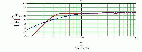 Fig.2-1
 Sound pressure level
 Fig.2-2
 The sound pressure level of the open end and the driver
Resonance will be occurred at (2n-1)λ /4, but the higher frequency is absorbed more than lower by the acoustic stuff, so we can neglect the high order member of the resonance equation.
In order to get a resistive acoustic impedance, the midbass driver was offset 28cm from the closed end of the pipe. This offset brings the less high frequency leakage, and wider resistive range for the acoustic impedance phase.
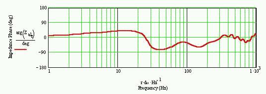
Fig.3 The phase response of acoustic impedance
The above figure-3 shows the phase characteristic of an acoustic impedance.
The figure shows that the acoustic impedance is resistive around above 300Hz. Smaller offset position seems to often bring reactive acoustic impedance unexpectedly at some frequencies.
However, small offset seems to a little bit better for the amplitude response at the mid-range, but it brings reactive acoustic impedance around 300Hz, so it depends on how to think about the important characteristics.
Later, you can find the figure 6 which shows the absolute value of acoustic impedance of TLS, we can know that the acoustic impedance becomes reactive around 100Hz to 200Hz in figure 3 because of the resonance peak around 120Hz in figure 6.
If we desire only low frequency range as important, it is possible to achieve the characteristic in figure 4.
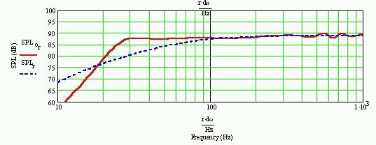
Fig.4 A design example aimed at super-low
By this design, f-3 point is around 25Hz, -10dB is below the 20Hz.
However, a cabinet size becomes more than three times. I think this is stupid design.
I just show the it is possible to achieve this characteristics with 18cm driver, that is all. Please do not try seriously like this stupid design ;)
By my calculation, TLS may easily become the flat response by narrowed down line from one fourth of whole length. Dr. King designed straight line with the Focal driver, but it also can be wider low range and reduce the ripple by narrowing down the 1/4 tip of his design, like as shown in figure 5.
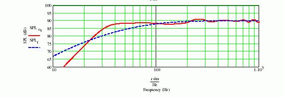
Fig.5 The example of a design with Focal
Please find the above figure 5, which I changed the design of Dr. King's at the tip from 1/4 narrowed down to Sd/2, and NO acoustic stuff is filled at this 1/4 tip.
A guy recently seemed to write this method in his article, but now I would like to clarify this is my original idea.
Other design is the completely same as Dr. King's.
In other words, we can get the two advantages by narrowing down the line tip. One is less ripple (low pass filtering), and the other is we can shorten the line length (lowering the resonance if the same length).
(Furthermore, clearly the enclosure size will be smaller.)
The higher order resonant peaks do not be lower by narrowing tip, but fundamental resonance becomes lower, so high frequency from the open end can be suppressed.
At first, I considered this phenomenon (fundamental resonance becomes lower) may be explained by the open end compensation coefficient.
In order that open end compensation of air column resonance may be close to full reflection by the narrowed open end. Therefore, the compensation coefficient may become large if narrowing down, then it may lower the resonant frequency.
On resonance frequency, reflection should be occurred at the open end primarily. (without reflection, the resonance cannot occur.)
It is the cause of the inertia of air that the open end compensation arises, if it says. Particle velocity will become quick by narrowed open end.
Then, a inertia becomes large. Therefore, a reflective point goes far from the open end.
λ = 4 (L+x)
here, L: The length of a line, x:open end compensation coefficient.
However, please notice that the higher order resonance like as 5λ /4 does not become lower.
And unfortunately, by above method, we cannot explain why higher order components does not become lower.
From another point of view, the resonating frequency can be lower if wavelength was shortened, and it is considered with since acoustic velocity falls.
When the cross-section area of a line is shown 'S', particle velocity of a medium (an air) is 'u' and sound pressure 'p', Acoustic impedance can be written as
Za = p/(S·u) .
When acoustic velocity is 'c' and a density of medium is ρ, peculiar acoustic impedance is: Z =ρ·c
therefore
ρ·c = p/u
Here, ρ is a fixed value clearly. the particle velocity will be faster if narrowing the open end, so the sound velocity has been fallen? -- conversely, if this idea is correct, extracted open end like as exponential horn brings higher sound velocity? --This is real high speed sound, isn't it? ;-)
So, TLS is real low speed sound, it is not worth to listen :-]
(You know, 'High speed sound' is No sense for scientific eyes. It does NOT concern to the sound velocity or particle velocity.)
Although many things were written, I do not have an enough confidence in fact, because still I do not have an explanation to the high order mode resonance.
:-c
Of course, this phenomenon that high order frequency does not fall (this is true without any doubt) is suitable for the speaker system. Because it is easy to stop higher frequency with a small amount of acoustic stuff. Inversely, if the high order resonance become lower together with fundamental, it is difficult to damp.
By my calculation, the peak frequency of absolute value of the acoustic impedance becomes lower, but high order does not by the narrowed tip of the line. therefore, we can get the suitable characteristic with shorter line. (Figure 6 below)
Fundamental resonance becomes almost 1/4 of 3rd order resonance.
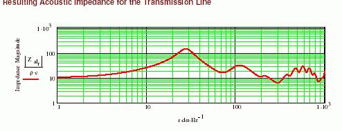
Fig.6 The absolute value of acoustic impedance
The boundary conditions of a wave equation can be known, then differential equation can be solved, a numerical simulation result is obtained, and the result is Fig.6.
You may ask me, "OK, you can understand the wave equation. And it has checked that high order resonance frequencies did not lower as a result, so it is enough, isn't it?"
It may be truth just as a scientific topic, and I can understand it, but I am not convinced.
In other words, I think generally we cannot be convinced heartily without understandable concrete physical model.
A resonance frequency is the frequency on which the denominator polynomial of the wave equation approaches zero. Therefore, near by the resonance frequency the acoustic impedance inside the line is going up, just the same as resonance of LC filter.
Extremely, if the cross section of the line has been changed suddenly, of cause it gives acoustic low-pass filter, especially if there is less acoustic stuff. By this method, therefore we can reduce the high frequency leakage from the open end.
If we can reduce the high frequency leakage, it will decrease the interference to the front of the driver, so ripple of the frequency response can be reduced, and also low frequency level becomes higher.
However, clearly such method means close to the bass reflex enclosure, and I think the advantage of TLS is not expectable.
Therefore, I narrow down a line smoothly and am taking care not to construct a definite acoustic filter.
Of course, even if the open end narrowed down smoothly, the absolute value of the acoustic impedance becomes higher by the smaller open end. However, if the impedance is resistive, the driver is just only damped so I think the problem is small. (The problem of nonlinearity of the acoustic stuff may remain.)
In my design, I took care of this characteristic, i.e., resistive as much as possible, and then extended the low end frequency. Because, I think it is the point by which TLS is characterized.
Additionally, I take this occasion to say that the Vifa tweeter which I selected also announced "Non reflective dual chamber".
From the amplitude response, the smooth narrowing down open end is not required but you can get the similar response if you have added the "port". (Operation is more close to a bass reflex in that case - probably I may say ML-TQWT.)
By my method, narrowed down smoothly, if there are few acoustic stuffs, phase of the open end is close to the driver around the resonance frequency.
That is, reflection at the open end on resonance frequency becomes clear (but still it is not quite a clear as a bass reflex or ML-TQWT)
With the same condition of transmission line but just reducing the acoustic stuff, the same phase frequency range becomes narrow. Although still we can find the signs of reflection but it does not equal to the bass-reflex or ML-TQWT. The phase response of driver and open end are not so matched as bass-reflex. (Please see figure 7.)
As a result, the response from the open end becomes the broad characteristic. Below a resonance frequency, the response becomes more gentle, very low frequency response does not descend steeply rather than a bass reflex. A red solid line is phase transition of the open end, and a blue dotted line shows driver side.
Fig.7 Comparison of the phase of the open end and a driver
Here, I state to the characteristics of the bass reflex. The following figure 8 shows the phase response simulation of the almost same size as figure 7.
As you can find, phase responses of two outputs coincide over 1 decade.
A blue dotted line is the port output.
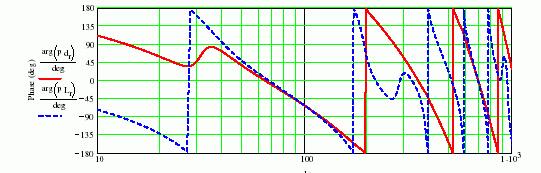
Fig.8 The phase response of the port and the driver with a bass reflex
enclosure
Below figure 9 shows the sound pressure level of a bass reflex enclosure. Here, its vent area and the volume are the almost same as TLS of my design.
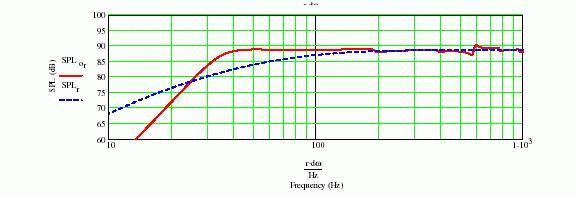
Fig.9 The amplitude characteristic of a bass reflex
This frequency amplitude response is flatter than TLS if restricted 40 to 100 Hz, but we can find the sudden changing of amplitude and phase at middle range.
The reason of this response is due to the high pressure load on back side, and it is reactive without damping.
Please be care also near 20Hz or lower, the level is lower than TLS. At a low end, so it is close to the no damping.
Electric impedance peak becomes higher than TLS, and its frequency also. And, phase rotation on low end becomes large. (That is, Q becomes high.)
Here, the acoustic impedance of a bass reflex box can be shown by the following figure 10.
It is clearly reactive at full range. I think the difference from TLS will be clear. (It is so reactive when the phase is close to }90 degrees)
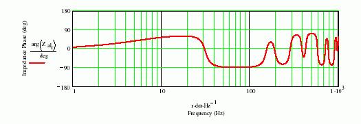
Fig.10 A bass reflex, the phase characteristic of acoustic impedance
Electric impedance of TLS is also different from bass-reflex. A simulation result is shown in the following figure 11.
 Fig. 11
 The electric impedance characteristic of TLS
A peak becomes lower than the usual bass reflex, as it is damped by the acoustic stuff.
The peak frequency is also lower.
A final drawing (pdf file) is here. The shade in this drawing means the acoustic stuff.
The material of the yellow part in a drawing is a hinoki (Japanese cypress) triangular block, and I bought them at the DIY shop. I used properly 18mm, 12mm, and 8mm widths.
About the acoustic stuff, I used 50g of the glass wool nearby the open end, and others are ester wool.
Ester wool is used about 200g for one channel. The wool filter for the glass tank of the tropical fish is quite suitable.
As density of a acoustic stuff, at the beginning of 50cm is 8[kg/m3 ], and then middle is 4[kg/m3]. I changed the density from the design value when adjustment. Please notice, it is very important that NO acoustic stuff inserted near the open end.
By changing the acoustic stuff density, the resonance frequency does not change so much, as you can easily understand if you calculate.
However, since it will change the characteristic if you put into the narrowed part of the line. So even when required, please limit to the minimum quantity.
Attenuation of the glass wool in a high frequency is far larger than ester wool (it is different also 10 times), so I employed it to suppress the higher frequency from the open end. If decrease the acoustic stuff, the lower level will be higher, but high frequency leakage also will increase.
By employing the glass wool, high frequency leakage might be smaller and low frequency level larger at once · · · Hopefully.
If you do not need an extreme wide range, line length can be shortened, so the box size can be smaller than my design.
As I designed from the Japanese standard board size, which is 2430mm·1220mm, so the cost will be the same if smaller. Please find this pdf file, this is board cutting form the standard size.
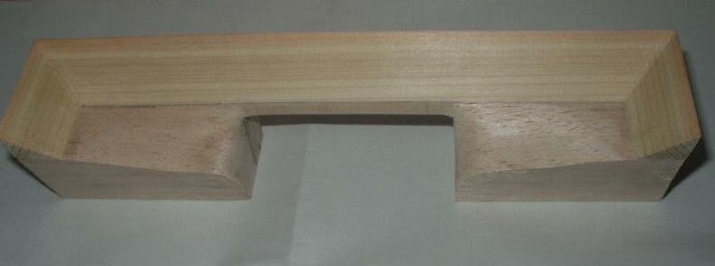
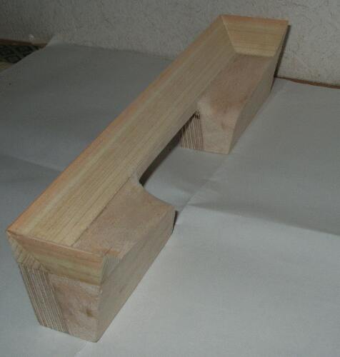
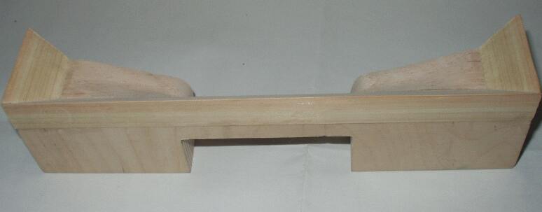
Although near a open end is not easily understandable without 3D-CAD. Therefore, please give up... it will not be allowed ;), so please find from photographs, somehow.
In short, it is narrowing down towards the tip smoothly. Therefore, I made above port block from the white birch plywood, triangular hinoki, and balsa block.
The picture becomes big by click.
New window opens by click, please close it by the browser button.
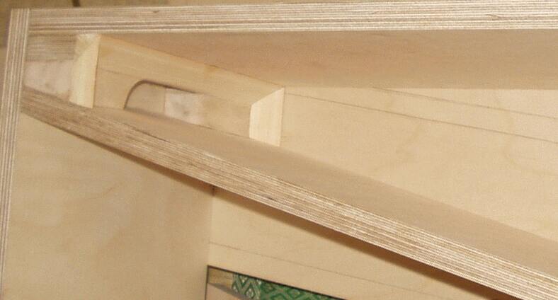
The lower photograph constructed the tip part.
Open end area is 0.0024[m2], therefore, Width 24[cm] by Height 1 [cm] is the same area.
If we made 1 [cm] crevice for the open end of this line, we may say there is no need such troublesome workmanship.
This idea is correct on acoustics theory, however still it is questionable on dynamics.
Please consider what 'the sound' is. It is the changing of the atmospheric pressure of an air.
It should be close to plane wave inside the line, and the velocity of the air flow increases if narrowing the open end.
According to Bernoulli's theorem, big power should work to the wall near the narrowed open end, due to the flow velocity ratio.
I think it vibrates the wall of the line open end, and then losing energy and sounding a box vainly.
Therefore, I think I had better to avoid the very flat open end. So I made this complex style for strengthness.
I employed slant baffle, and it is suitable for the narrowing open end, but it is explained at the next page as it is related to the network filter.
I already talk about manufacturing, but the next page is the design of a network, and making box.
* I wrote all parameters with SI units. If you do not know SI, please read here.
Next
Back to index
English home
Home
9th/Nov./2004 Last update
Copy right : Katsu