Japanese English
The design of a LC network filter
and the enclousure manufacturing
Maybe, there is no need to talk about the enclousure manufacturing, it is just a pride of my skill, in a word :-D
Baffle diffraction and LC network filter
Since baffle has an finite area, so the sound wave diffracts, if the wave
length is longer than baffle basically.
The lower frequency level will be higher with large baffle, but larger
baffle is not ideal.
If you can make 3 metre widths, maybe you can feel enough low level, but
of cause this is not realistic.
You may need a baffle with realistic area, then you need a compensation
filter, but it is more difficult to make a lower cut off frequency filter.
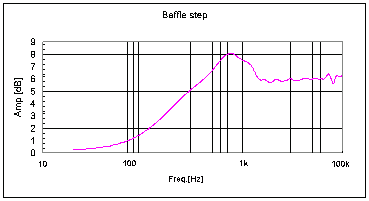
Please find the figure 1. This is the rough characteristic of baffle with
my design.
The edge of baffle is rounded, so the higher frequency ripple (almost above 3kHz) will be suppressed, but still the peak around 1 kHz will remain. (Please notice, if you employ the real sphere box, the ripple can be suppressed but still you will found the high frequency level becomes larger.)
Fig.1
Unfortunately, the midbass driver has a peak around this frequency, so
I need to lower this peak.
I think I need to compensate around 4dB at this frequency by the midbass driver characteristic and a baffle steps.
Near field measurement result is very similar to the maker's anouncement.
I tried to compensate the baffle characteristic by the LC network filter.
Simply saying, I made a dip at the cross over point, and then the peak
level could be lowered.
Additionally, midbass range is compensated by adjusting the time constant
of the low pass filter.
Higher range can be changed by the attenuater.
I think you can image by this simple explanation.
I do not like to inserting the LR or CR filter for the baffle step correction, because it means the electric power is consumed by the resister at middle
range.
If we need a simple shelving filter, we can compensate by adding the exclusive tone controller to our control amplifier, and it does not consume unnecessary power. Let us be tender to the environment ;)
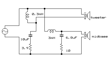
You can find the schematics below. Please notice, the tweeter polarity
is reversed.
Inductor characteristic impacts to the filter characteristic, so I employed
lower resistance iron core inductor of Jantzen.
 Fig.2
Fig.2
At first, I used series network, but I changed to the normal style.
The characteristic of the series type which I had used firstly and the characteristic of current circuit is almost same, but the rebounding was found at low frequency of the high-pass filter for series network (beneath -30dB).
Although, I cannot find the difference with my ears ;)
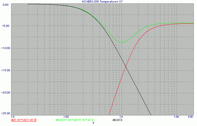
The characteristic shown in Fig 3 is slightly different with series type, but it is really subtle.
The level at 200Hz to 500Hz becomes 0.2 to 0.5dB higher.
The attenuater of the tweeter is not a constant impedance type, but it is a simple series register.
I decide it from the required attenuation level and the impedance of the tweeter.
Figure 3 shows the simulation, synthesized characteristic of tweeter and midbass, including the difference of the driver efficiencies.
Here you can find the compensation level is not 6dB but around 4.5dB.
I considered that the room gain becomes higher at lower frequency generally,
and normally the speaker would be set nearby the wall, so I decide it as
I think fit (by guesswork), and I did not adjust it after measurement.
But from the measurement value, I have very good sixth sense. :-D
(The ripple at very low frequency cannot compensate, it is the characteristic
of my room)
However, the tweeter has a small peak around 5kHz, and we can find it
at the final response.
 Fig.3
Fig.3
The filter characteristic may be an irregular, but of cause the purpose of the filter is flat response.
Japanese DIYers rarely make filters like this style, but in my opinion they need to consider what is fundamental ;)
You may feel it seems to be very low cross-over frequency, but this is the result for the peak of the driver and baffle step was considered. So real cross over frequency is around 2kHz or more.
You may understand it if considering the cut off frequency of tweeter is around 2.5kHz, but the final response is almost flat at middle range.
As far as I heard, Shibuya-san, a Japanese, uses similar filter,
so this style of filter might be called "Katsz-Shibuyan Filter" :-)
Anyway, I cannot understand that the maximum amplitude flat filter with
constant voltage addition is called "Linkwitz-Riley".
Because, Butterworth filter does not mean that the constant wattage addition filter, but it
means maximum flat response. Therefore, Linkwitz-Riley
means a kind of Butterworth filter using different crossover frequency for
high pass and low pass.
Furthermore, as far as I know this style has been already invented long
ago by Japanese in early seventies.
And it was published from MJ magazine. Therefore Linkwitz
and Riley are the second inventors, but anyway I think this filter should
be called "Butterworth", because there is nothing special as a filter itself.
And, the name Linkwitz-Riley
is rarely used in Japan.
The baffle is slanted in order to adjust two driver's positions. This
is important for the filter characteristic, because above simulated response
can be got if the driver position is the same.
In my personal opinion, the driver's position is important just only for the flat amplitude response.
Some manufactures use 6dB/oct filters, like Dynaudio or Meadowlark audio,
and they seems to be admired, but I believe such an admiration is not due
to the time response or wave synthesis.
I do not think it is good idea to make a difference to the baffle level for the purpose of adjusting the driver position, because the baffle response will be complex, moreover such baffle makes reflection to the tweeter. Therefore
I think slant baffle is better choice.
Two drivers are set to the centre of the baffle, symmetrical to the centre
line. The ripple level can be smaller by shift the driver's centre, if the distance from the ear is the same as centre setting. However, please notice,
that the distance should be considered by the three dimensional length, and
if the distance is changed it makes another influence by two driver's phase.
"Too much scheming will be the schemer's downfall"
Manufacturing box
All we need for manufacturing is "Guts" and "Effort", which I believe
:-D
You have to be thorough in your work with enough time as you can believe
your job, please spend your time and effort, that is all.
I bought 13 ply (18mm thickness) Finland-birch, at Shin-kiba where we
Japanese can buy plywood or wood materials with very cheap prices. The plywood was cut at that shop, a timber dealer.
However, the cutting accuracy does not seem to be better than a store
specializing in woodwork.
The manufacture method
1. At first, I made uniform width for all parts with using a plane and a rasp. By slant cutting, the board width got warped, so it was needed to modify.
2. I already talk about manufacturing the open end. Clearly it is impossible to make it later;)
3. I wrote drawings on the side wall of the speaker, the place of all
parts. I pasted all parts together with side board, so the drawing should
be written in accurate.
4. I have started to manufacture from the open end, and then I pasted all parts over with the side board, from near the open end in turn. I think
if I paste all parts at once, it will bring the unsuccessful result.
In order to make in accurate, I used many clamps and temporary constructed,
and carried out.
5. After making an acoustic path, then I pasted reinforcement parts. I
have needed some modifying for those parts. "Anima" (sound post) of the violin should be inserted in the end of manufacture, but I inserted this reinforcement before pasting the board of the another side.
6. I made holes for the insert nut and screw to the bottom side.
The bottom can be removal in order to adjust the acoustic stuff.
7. Making a holes to the baffle for the insert nut, but I think if you
do not have enough confidence to make accurate, I do not recommend to use
insert nut. Wood screws or truss screws may be easier.
Biding posts should be put before pasting together the both side. Of
cause, driver hook up wires and metal fitting to the driver are also.
Here, I inserted the acoustic stuff. Biding posts are individual for the
tweeter and midbass.
8. I pasted another side plank with using many clamps. Then I rounded
corners of baffle with using a plane and rasp.
9 In last, after the adhesive agent is parched, I sanded down with #120
sandpaper.
Painting
The next step is painting. I believe we need "Guts" for painting
more than manufacturing :-D
I spent more than three weeks for painting, but I think I would spend
more if I had painted in winter. (I painted in summer)
I used colour urethane-varnish, 2 by 270[ml] bottle, and 2 spray cans
of 450[ml]
1. First of all, please notice that good painting can be achieved by good
sanding before paint.
2. I made thin varnish with a solvent, almost double. I painted it twice.
3. Then painting more thick varnish with a brush.
4. After paint dried (it takes 24 hours at least, even in Summer), then I polished wet sanding with #240 waterproof sandpaper.
5. Paint and wet sand several times with using a small brush for the modelling.
If you choose a big brush like as used for painting walls, I think
it sometimes brings unevenness.
6. After the surface becomes smooth enough, spray has to be used for the
finish, at outside or in the room where ventilation is thorough sufficiently.
Air brush is the best choice for good finish, but small air brush is difficult to paint wide area. It is need to mask the place where it does not paint, and we also need the mask it does in the face. Painting is not good for your health, especially the solvent of varnish.
7. I polished by wet sanding again with using with #400 waterproof sandpaper,
then spray again, then wet sand #600.
8. The butt end of the finland birch plywood is far better than other plywood
or MDF, but occasionally there is a hole or pore at the butt end. I painted
the putty to such holes or lacking. The putty was made by the same coloured
varnish and the refuse of shaving wood.
9. In last, spray the paint thickly. Finish should be thick in my opinion, because thin painting sometimes brings failure for the finish. Using a stand,
slanted baffle has to be parallel to the land when painting.
10. After paint is dried, I put drivers on. Then, we MUST smile and chuckle
alone with seeing a curtain is reflecting to the painted surface :-D.
Maybe you will chuckle three days, then you satisfied with.
I had measured after that, but still network filter was not equipped.
The tweeter level, cut off frequency or other parameters might be adjusted
to your room after measurement.
Next
Back to index
English home
Home
9th/Sep./2004 Last update
Copy right : Katsu


